|
<< Click to Display Table of Contents >> Duct Data Example |
  
|
|
<< Click to Display Table of Contents >> Duct Data Example |
|
Here is an example of how to enter a simple duct system on the Duct Data page. In this example we will do the following:
1. Create a new project.
2. Add all the ducts in the correct layout.
3. Assign various duct properties.
4. Assign fittings to each duct.
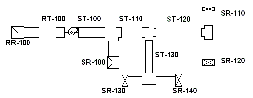
The following is a layout showing how the ducts are connected together (the drawing is for illustration purposes only, since there is no drawing capability in Rhvac Online):
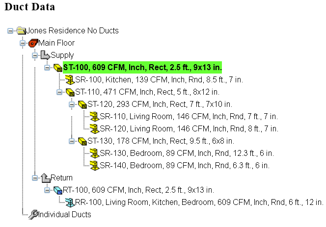
Here is how the Duct Data page will look after creating all of the ducts:
Steps to create the above example.
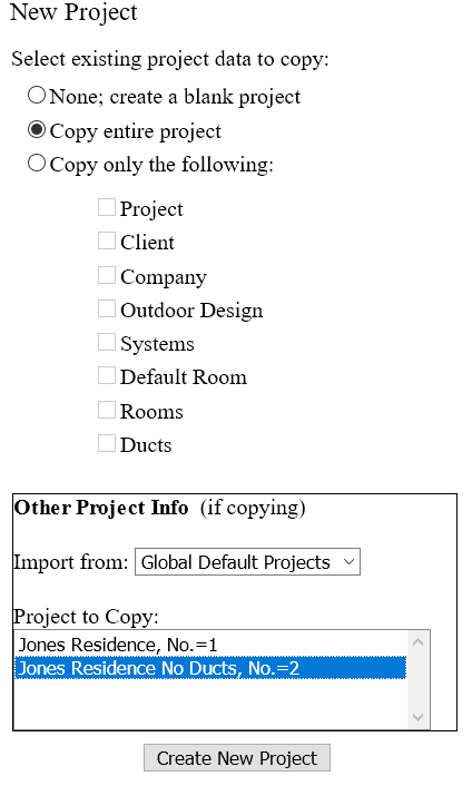
1. Create a new project. The project you need for this example is one that already has rooms, but no ductwork. Click the menu, "File | New Project". Then on the New Project page, for the "Select existing project data to copy" option select "Copy entire project". Then for the Import From option select "Global Default Projects". And then under "Project to Copy" select the file named, "Jones Residence No Ducts" from the list. Finally, click the "Create New Project" button at the bottom of the page, as shown below.
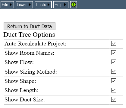
2. Turn on all the duct tree options. In order to see room names, duct sizes, etc., in the tree we need to turn on all the options to show extra data in the duct tree. Click the menu, "Ducts | Duct Tree Options" to go to the Duct Tree Options page. Check all the boxes, as shown below, then click the Return to Duct Data button.
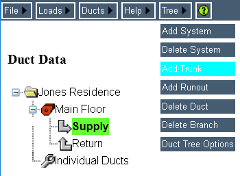
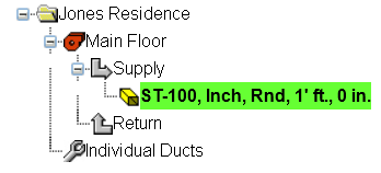
3. Create the supply main trunk. First click the Supply arrow node, then click the menu, "Tree | Add Trunk". The appearance of the page before and after is shown below.
Before:
After:
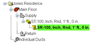
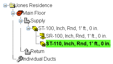
4. Add the first takeoff. With trunk ST-100 selected in the tree (it's highlighted in green, as shown above), click the menu, "Tree | Add Runout". After doing that, the tree layout should look like the following:
5. Add the next trunk. First select trunk ST-100 again, then click the menu, "Tree | Add Trunk". Then the layout will look like this:
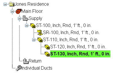
6. Add the final two trunks. Now we need to enter the two trunks that are downstream of ST-110. First select trunk ST-110, then click the menu, "Tree | Add Trunk" to add trunk ST-120. Then select trunk ST-110 again, and again click the menu, "Tree | Add Trunk" to add trunk ST-130. The layout will then look as follows:
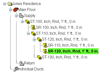
7. Add the two runouts for the Living Room. Select trunk ST-120, then click the menu, "Tree | Add Runout". That will add runout SR-110. Then select trunk ST-120 again, and click the menu, "Tree | Add Runout" to add runout SR-120. The layout will then look as follows:
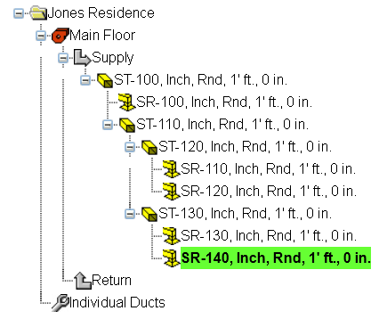
8. Add the two runouts for the Bedroom. Select trunk ST-130, then click the menu, "Tree | Add Runout". That will add runout SR-130. Then select trunk ST-130 again, and click the menu, "Tree | Add Runout" to add runout SR-140.
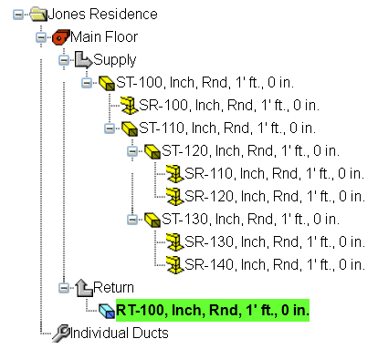
9. Add the return main trunk: Now we'll add the return ducts. This example will include the minimum number of ducts needed to have a complete system: a trunk and a runout. We have to add the trunk first, so click on the Return arrow node, then click the menu, "Tree | Add Trunk". The return main trunk, named RT-100 will be added, as shown below:
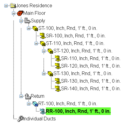
10. Add a return runout. With duct RT-100 still selected, click the menu, "Tree | Add Runout" to add runout RR-100. The page should then look like the following picture:
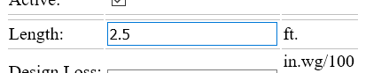
11. Assign a property to a duct. Let's start with the first trunk, ST-100, so click that duct in the tree and enter 2.5 for the Length input, as shown below.
12. Assign the Length property to the rest of the ducts. Starting with the next duct down in the tree, enter the Length property for the rest of the ducts:
Duct |
Length |
ST-100 |
2.5 |
SR-100 |
8.5 |
ST-110 |
5 |
ST-120 |
7 |
SR-110 |
7 |
SR-120 |
8 |
ST-130 |
9.5 |
SR-130 |
12.3 |
SR-140 |
6.3 |
RT-100 |
2.5 |
RR-100 |
6 |
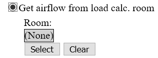
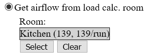
13. Assign a room to a supply runout. This duct design will be linked to the supply air of the rooms that were defined in the load calculation part of Rhvac Online. Click the runout named SR-100, then Select the option, "Get airflow from load calc. room". Then click the Select button for the Room input, shown below.
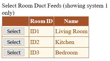
That will take you to the Select Duct Feeds page, shown below. Click the Select button for the Kitchen.
Now the Room input on the Duct Data page looks like this:
14. Assign rooms to the rest of the supply runouts. Now lets assign rooms to the rest of the supply runouts. Repeat the procedures of the previous step for each of the supply runouts using the following table.
Runout |
Room |
SR-100 |
Kitchen |
SR-110 |
Living Room |
SR-120 |
Living Room |
SR-130 |
Bedroom |
SR-140 |
Bedroom |
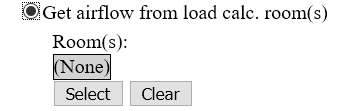
15. Assign all the rooms to the return runout. Unlike supply runouts, with return runouts you can assign multiple rooms to a runout duct to indicate that the runout is returning air from multiple rooms in the load calculation. Let's assign all of the System 1 rooms to the RR-100 runout. First, select RR-100 in the tree, then select "Get airflow from load calc. room(s)" option, shown below.
Next, click the Select button, shown above, to open the "Select Rooms for Return Duct" page, shown below.
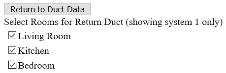
Check all the room boxes, as shown above, then click the "Return to Duct Data" button.
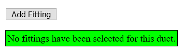
16. Assign a fitting to a duct. In order for the calculations to determine pressure losses in the system we need to assign fittings to each duct. First, select duct ST-100, then scroll down and click the Add Fitting button.
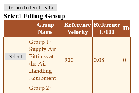
That will take you to the Select Fitting Group page, shown below. Click the Select button for the group named, "Group 1: Supply Air Fittings at the Air Handling Equipment".
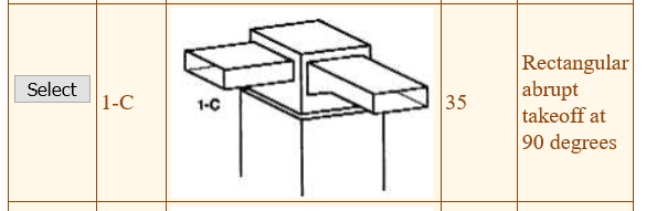
After you click Select, the Select Fitting page opens. Click the Select button beside fitting 1-C, shown below.
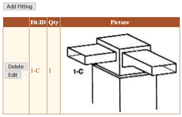
After you click Select for fitting 1-C, you are returned to the Duct Data page. Scroll down again to the fittings grid, which should now look like the following picture:
17. Assign junction fittings to ducts. Trunk ST-100 has two downstream ducts: SR-100 and ST-110. So we need to assign junction fitting ID's to both of those ducts. As you can see from the duct drawing at the top of this page, SR-100 takes off at a 90 degree angle with respect to the upstream duct, while ST-110 goes straight. So even though there is only one physical fitting connecting these three ducts together, we will need to define two fitting ID's to the downstream ducts to account for it.
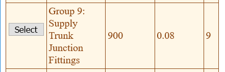
Scroll back up to the duct tree, and select duct SR-100. Then scroll back down and click the Add Fitting button. This time on the Select Fitting Group page, click the Select button for the group named, "Group 9: Supply Trunk Junction Fittings", shown below.
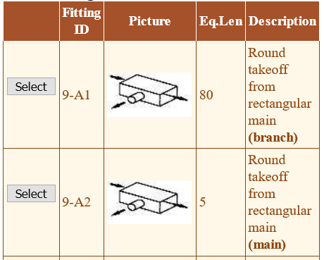
Next, on the Select Fitting page, click the Select button for fitting 9-A1. As you can see from the words "(branch)" and "(main)" in the descriptions, the 9A-1 fitting is for the angled outlet, while 9-A2 is for the straight outlet.
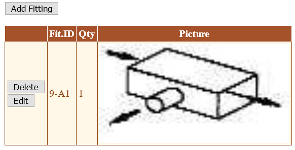
After selecting fitting 9-A1 the fittings area of the Duct Data page looks like this:
Now we need to select the fitting ID for the other duct downstream of ST-100, which is ST-110. So in the duct tree click duct ST-110, then scroll down to the fittings area and click Add Fitting. On the Select Fitting Group page click the Select button for Group 9. Then on the Select Fitting page click the Select button for fitting 9-A2. The fittings area of Duct Data page will then look like this:

18. Assign fittings and quantities to the remainder of the ducts. Following the above procedures assign fittings to the rest of the ducts, as follows.
Duct |
Fittings |
ST-100 |
1-C |
SR-100 |
9-A1 11-B (2) 4-H |
ST-110 |
9-A2 |
ST-120 |
9-E1 |
SR-110 |
11-A 11-B (2) 4-H |
SR-120 |
11-A 11-B (2) 4-H |
ST-130 |
9-E2 |
SR-130 |
11-A 11-B (2) 4-H |
SR-140 |
11-A 11-B (3) 4-H |
RT-100 |
5-C |
RR-100 |
6-F (group 6.2) |
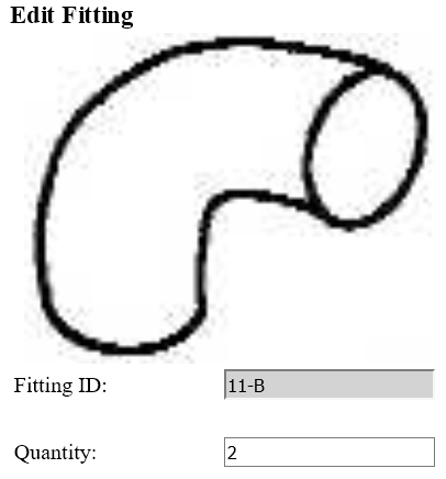
Notice that several of the fittings in the above list have a number in parentheses shown after the fitting ID, such as "11-B (2)". The number in parentheses indicates that you need to specify that the fitting occurs multiple times on the current duct. For example, click duct SR-100, then scroll down to the fittings grid and click the Edit button for the 11-B fitting. That will take you to the Edit Fitting page, shown below. Enter 2 in the Quantity input, then click Return to Duct Data.
Repeat the above procedure for each of the other ducts that have fittings with a quantity greater than 1.
19. Assign rectangular shape to some of the ducts. In this example, we want each of the trunk ducts to be rectangular in shape, while leaving all of the runouts round. We could select each trunk one by one and change the Shape option to Rectangular, but a quicker way is to do it with the Set Multiple Duct Properties page. Click the menu, "Ducts | Set Multiple Duct Properties". That takes you to the Set Multiple Duct Properties page.
On the Set Multiple Duct Properties page, follow these steps:
a.Click the "Mark All Trunks" button, as shown below.
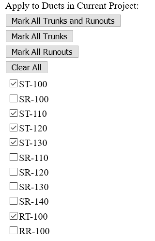
b.Click the Clear button at the top of the Include column.
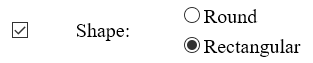
c.Check the Include checkbox for the Shape property.
d.Select the Rectangular option for the Shape property, as shown below.
e.Scroll to the bottom of the page, and click "Apply Settings to Selected Ducts".
After following the above steps, click "Return to Duct Data".
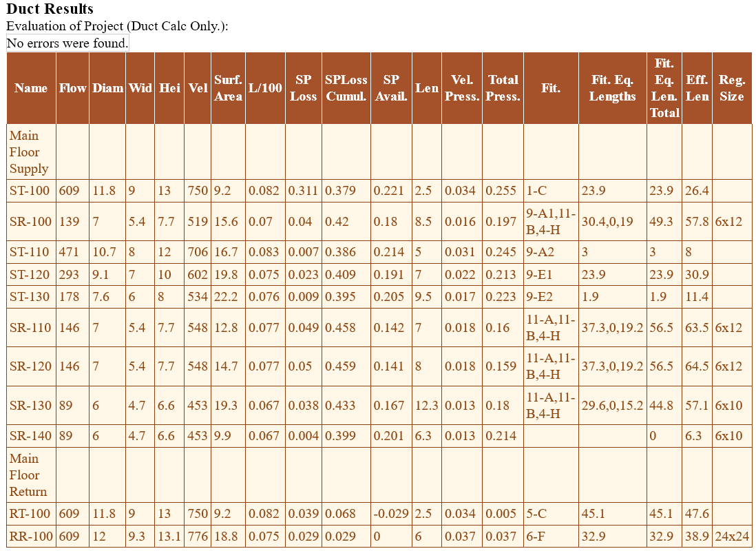
20. View the results. To see the results, click the menu, "Ducts | Duct Results Grid". The page should look like the following picture: