|
<< Click to Display Table of Contents >> Duct Data |
  
|
|
<< Click to Display Table of Contents >> Duct Data |
|
Click "Ducts | Duct Data" to open this page, which lets you design duct systems using a tree outline.
Also see: Duct Data Example
The Duct Data page lets you create one or more duct systems for the HVAC systems in your project that you have defined. A system node ![]() will be added to the tree for each system you have created. To begin adding ducts to a system, click on the Supply node
will be added to the tree for each system you have created. To begin adding ducts to a system, click on the Supply node ![]() that is directly under the system node, then click "Tree | Add Trunk". The first duct you create must be a trunk, then you can create more trunks and runouts.
that is directly under the system node, then click "Tree | Add Trunk". The first duct you create must be a trunk, then you can create more trunks and runouts.
Click on a system node or a duct node to edit that system or duct. The inputs below the tree will change as needed as you select different nodes in the tree.
Each duct has only one airflow and one size: As you are defining your ducts on this page, keep in mind that each "duct" you define has only one size and one airflow. In the following image, the sections marked A and B happen to be physically the same trunk duct, but since there is a takeoff (section C) in the middle of the duct, the airflow in section B is therefore less than that of section A, so you must enter A and B as separate ducts.
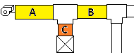
Here's another example to show when you need to define a trunk as two separate ducts. The sections marked A and B in the image below have the same airflow, but since section B is not the same size as section A, you must enter one trunk for section A and another trunk for section B.
![]()
Recalculate Button: The Recalculate button will appear if you have the Auto Recalculate Project option unchecked on the Duct Tree Options page.
Add System: Adds a new system node near the bottom of the tree.
Delete System: Deletes the current system. You cannot delete the only system, nor can you delete a system that has any ducts or rooms in it.
Add Trunk: Adds a new trunk duct below the currently selected node. The current node must be either a Supply node ![]() , a Return node
, a Return node ![]() , a trunk node
, a trunk node ![]() , or the Individual Ducts node
, or the Individual Ducts node ![]() for this button to function.
for this button to function.
Add Runout: Adds a new runout duct below the currently selected node. The current node has to be a trunk node ![]() for this button to function.
for this button to function.
Delete Duct: Deletes the current duct from the project. If it is a trunk duct, any ducts directly below the deleted duct will be reconnected to its upstream trunk.
Delete Branch: Deletes the current trunk and all ducts downstream of it.
Duct Tree Options: Goes to the Duct Tree Options page, where you can set appearance and behavior options for the tree.
Current Duct: Specifies the current duct. You can select a different duct using this input or by clicking a duct node in the tree.
Duct Name: Specifies the name you want to use for the duct. A name is generated for each duct at the time of its creation, but you can change the name if you like. The automatically generated names use the following prefixes:
Prefix |
Meaning |
|---|---|
ST |
Supply Trunk |
SR |
Supply Runout |
RT |
Return Trunk |
RR |
Return Runout |
Airflow Option: These two radio buttons let you select whether you want to enter the runout duct's airflow (Let me enter custom airflow) or get it from one of the rooms in the load calculation (Get airflow from load calc. room).
Custom Airflow: Specifies your custom airflow value for the runout. This value is only used if you select the "Let me enter custom airflow" option.
Custom Room Name (optional): Specifies the name you want to give to the duct. This name is only used if you select the "Let me enter custom airflow" option.
Make Custom Airflow the Default: Clicking this button sets the default for any new runouts you create to have the "Let me enter custom airflow" option already selected for the new duct.
Select: For supply runouts, opens the Select Room Duct Feeds page where you can select one of the rooms in the current system to which the runout supplies air. For return runouts, opens the Select Rooms for Return Ducts page where you can select one or more rooms in the current system from which the runout returns air.
Subtract Ventilation from Return Airflow: Makes it so the airflow assigned to the return system is equal to the supply airflow minus the ventilation airflow entered on the Ventilation Rate page, which is what you normally will want to do. Only in rare situations would you want to uncheck this box, to indicate that you want the return airflow to equal the supply airflow even when there is ventilation. This checkbox is only available if the current duct is a return main trunk. This checkbox has no effect if the current system does not have any ventilation.
Add Return Loss to Supply: Makes it so the cumulative static pressure loss through the return side is added to the first trunk of the supply side, which is what you normally want to happen. To instead isolate the return losses from the supply losses uncheck this box (not normally done). Note that this property also determines whether or not the return side's total effective length (TEL) is added to that of the supply side. This checkbox is only available if the current duct is a return main trunk.
Active: Specifies whether the current duct and any downstream of it (or upstream, if return) are included in the calculations.
Match Upstream Duct Size: Check this box if you would like this duct's size to match the size that will be used for the upstream duct (or downstream, for return ducts). This feature can be useful when you have a trunk with several takeoffs, and you do not want to downsize the trunk after each takeoff.
Disable Auto Diversity: Check this box to make it so if this trunk feeds rooms that are in more than one zone the airflow assigned to this trunk will not be automatically diversified (reduced). Normally you should leave this box unchecked to allow the program to assign the airflow through a trunk that feeds multiple zones to equal the sum of the downstream runout airflows calculated with Manual J's "Average Load Procedure."
Note that this property does not affect the airflows assigned to other trunks upstream or downstream from this trunk.
Length: Specifies the length of the duct, in feet (or feet and inches). The length of the duct is used with the calculated frictional loss per 100 feet to determine the static pressure loss for the duct.
To enter the length in feet and inches, type the feet, then a dash, then the inches.
Design Loss: Specifies the loss per 100 ft. that you want the calculations to aim for when calculating the duct's size. The actual loss calculated and reported for the duct may be different from the value you enter here, depending on several factors, such as velocity or height constraints, etc..
Shape: Specifies whether you want the duct to be round or rectangular in shape.
Temp. (Temperature): Specifies the temperature of the air within the duct, which has a small effect on the sizing calculations.
Material: Specifies which duct material (abbreviated) to use for the duct. Click the Select button to select from a list of duct materials.
Select: Opens the Duct Material page where you can select from a list of pre-defined duct materials and roughness factors.
Roughness: Specifies the relative roughness of the duct material, which affects the pressure loss of the air moving through the duct due to friction with the duct walls.
Minimum Height, Maximum Height: Specifies either a constraint on the diameter or height of the duct, depending on whether the shape is round or rectangular. If there is no height constraint, this input may be left as zero.
Minimum Velocity: Specifies an optional smallest allowable velocity for the duct when the calculations are determining the duct size. If you do not have a minimum velocity requirement leave this input at zero.
Maximum Velocity: Specifies an optional desired maximum duct air velocity. If you do not have a maximum velocity requirement leave this input at zero. The following list of maximum velocities is from ACCA Manual D.
System Type |
Duct Type |
Description |
Flex or Rigid |
Maximum Velocity |
|---|---|---|---|---|
Supply |
Trunk |
Conservative |
Rigid |
700 |
Supply |
Trunk |
Conservative |
Flex |
700 |
Supply |
Trunk |
Maximum |
Rigid |
900 |
Supply |
Trunk |
Maximum |
Flex |
900 |
Supply |
Branch |
Conservative |
Rigid |
600 |
Supply |
Branch |
Conservative |
Flex |
700 |
Supply |
Branch |
Maximum |
Rigid |
900 |
Supply |
Branch |
Maximum |
Flex |
900 |
Return |
Trunk |
Conservative |
Rigid |
600 |
Return |
Trunk |
Conservative |
Flex |
600 |
Return |
Trunk |
Maximum |
Rigid |
700 |
Return |
Trunk |
Maximum |
Flex |
700 |
Return |
Branch |
Conservative |
Rigid |
500 |
Return |
Branch |
Conservative |
Flex |
600 |
Return |
Branch |
Maximum |
Rigid |
700 |
Return |
Branch |
Maximum |
Flex |
700 |
Sizing Method: Specifies the sizing option to use for this duct. Note that if you use the "Sched" option (to use the duct schedule), the sizing calculations will limit the calculated duct diameter or width to be one that occurs in the duct schedule on the Duct Schedule for Current Project page.
Option |
Description |
|---|---|
Inch |
Calculate sizes to the nearest inch. |
Exact |
Calculate sizes exactly without adjusting them to the nearest whole numbers. |
Sched |
Limit the calculated diameter or width to be from the duct schedule for the project. |
Presize |
Use the sizes specified in the Presize Diameter, Presize Width, and Presize Height inputs. |
Presize Diameter, Width and Height: Specifies the user-defined size of the duct. These inputs are used only if you set the "Sizing Method" input to Presize. Otherwise, leave them at zero. You can then use these inputs to specify the fixed size that you want for the duct calculations. For round ducts, enter the diameter. For rectangular ducts, enter the width and height.
Duct Load Factor Scenario: Specifies which of your 5 duct load factor scenarios to which to assign this duct. In on the Duct Load Factors page you can enter up to 5 scenarios to account for different locations that the ducts in a system are located in. For example, some of the ductwork in a system may be in an unconditioned basement, some within the conditioned space, and the rest in an attic. This property lets you enter a scenario number so that this duct's surface area will be included in the proper location scenario when Rhvac Online calculates the duct surface area.
If your ductwork in this system is all within the same kind of location, select option 1. If it is in different kinds of locations, select an appropriate scenario number from 1 to 5 (scenarios themselves are defined on the Duct Load Factors page). If this duct is in a conditioned space select zero for this value so this duct's surface area will not contribute to the duct loads for this system.
Add Fitting Button: Opens the Select Fitting Group page, where you can begin adding a fitting to the current duct. After you add a fitting it will show in the fitting grid.
If you have not yet assigned any fittings to the current duct this grid will show a green text box (shown below) saying, "No fittings have been selected for this duct."
![]()
After adding fittings, the grid will look something like the following picture:
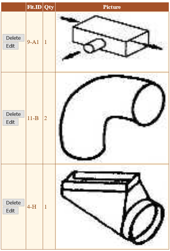
Delete Button: Deletes the fitting after asking you to confirm that you want to delete it.
Edit Button: Opens the Edit Fitting page, where you can specify things such as the fitting quantity and the angle of an elbow fitting.
Save and Calculate Button: Updates the calculation results at the bottom of this page. This button is only available for runout ducts.
Results (L/100, Velocity, Width, Height, Diameter): Shows the calculation results for the current runout duct. Only available if the current duct is a runout.